![]() 全国销售热线
全国销售热线
0415-3137582

丹东东华测控有限公司
联系人:王经理
手机:13700157341
销售部:张部长
手机:13030750998
电话:0415-3137582
传真:0415-3137583
邮箱:dhckjs@aliyun.com
网址:www.dhckjs.com
地址:辽宁(丹东)仪器仪表产业基地启动区标准厂房11#楼第6层
Operation Instructions for QZL Gas Mass Flowmeter
1.Features and Applications
Gas mass Flowmeter is suitable for carrying on the precision measurement to the gaseous mass. It will transform the gaseous mass flow into the gas volume flow or the gaseous mass flow both of which are under the corresponding standard state.
Gas mass Flowmeter possess the characteristics of high precision, long life, good repetition, wide flow range , stable reliability etc. It is in the leading position of China to carry on the flow measurement with the method of measuring gaseous mass at present .
2.Main Technical Specification
Table 1


2.1 Standard m³indicates 1 cubic size gas under standard state ;
Standard state regulation:Pressure P=101.305KPaTemperature T=293.15K(20℃)
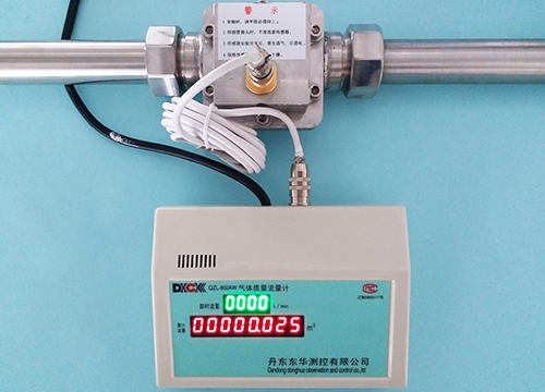
2.2 After biggest accumulation gas flow beyond position, it will reset automatically and cycle count . The indicating value decimal point is possible to retain the ml level, the user could make option.
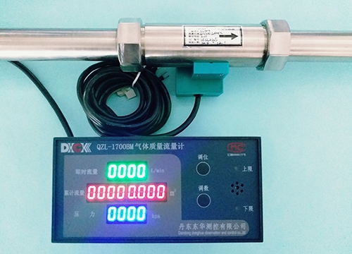
2.3 The timely flow demonstrates 4 figures, the accumulation flow demonstrates 8 figures, the pressure demonstrates 3 figures.
2.4 Type BM/BW has the functions of setting timely flow and pressure bound, ultra limits acousto-optic warning .
2.5 Other special function request


Maximum prompt flow:200L/min
5.Principle of Operation
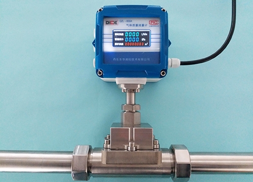
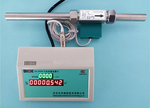
Gas mass flowmeter consist of airflow mass sensor and digital display integrating instrument.
Gas mass flowmeter employs American Micro Bridge Company's airflow mass sensor and pressure sensor. Airflow mass sensor bases on the heat transfer principle of heat which was carried off by airflow mass flowing through the sensor is in proportion to the output voltage. Pressure sensor means the pressure of gas is in proportion to output voltage, both of which means gas mass flow and gas pressure were outputed by transforming into analog signal simultaneously.
The function of digital display integrating instrument is to transform airflow mass's analog signal which was outputed by airflow mass sensor into digital signal thought the single-chip microcomputer's interior A∕D. Then after operation processing, it transforms the gas
mass flow into volume flow or mass flow both of which are under the standard states. Also after the data processing operation, it calculates the immediate flow and the accumulation flow separately, after that it's delivered to four and eight nixietube to display.
The other function of digital display integrating instrument is to transform gas pressure's analog signal which was outputed by pressure sensor into A/D mode thought the single-chip microcomputer, then calculating and processing the figure of gas pressure, after that delivering the figure to three nixietube to display.
Moreover, the single-chip microcomputer may preserve the data information into single-chip microcomputer's EEPROM permanently. The data information includes the related operation processing's various constant, coefficient and the bound of immediate flow and pressure which were established by manual setting. The single-chip microcomputer may also store the accumulated flow figures into EEPROM memorizer. These above data message may be preserved automatically after power cut , after power being supplied again, these data message may become self-recovery.
6.Installment and Connection
6 .1 Airflow Mass Sensor
6.1 .1 The sensor's outline drawing of the flow scope between 0~250L/min(please see picture 1)


7、Manipulation
7.1Inspection on if the gas mass flowmeter connection installment is unmistakable
7.2This instrument doesn't have alternating current switch, when the exterior alternating current puts through, this instrument then works.
7.3preheating 10 minutes after this instrument starting,then it could work normally.
7.4The setting methods of address code ,bound immediate flow and pressure flow with pressure display flowmeter are as follows:
Step 1:Presses down flowmeter's adjusting button for 3 seconds, The immediate flow window presents `Ad01' (‘Ad01’means the address code of flowmeter and the computer communication, it may be set from 01 to the maximum 99 ), And `0 ' are flashing, if the address code of `0 ' needs to change, please press the adjusting-number button to set the needed numerical value, if it does need to change, please press the adjusting-position button again to location jump, Then according to the needs to press adjusting-number button to transform the numerical value, After the establishment finished, press the adjusting- position button, if the upper limit indicating lamp is bright, it indicates that the address code has finished the establishment.
Step 2:When the upper limit indicating lamp is bright, the `0 ' in kilobit are flashing, please start to set the immediate flow upper limit's parameter, if the kilobit needs changing, you could press the adjusting-number button to change the numerical value, if it does not need changing, please press the the adjusting- position button again to location jump(hundred place, ten's place and unit's digit,The rest can be done in the same manner)After four figure values has been set one by one, press the the adjustingposition button, The lower limit indicating lamp is bright, which indicates the immediate flow upper limit has been finished establishment.
Step 3:When the lower limit indicating lamp is bright, the `0 ' in kilobit are flashing, please start to set the immediate flow lower limit's parameter, the operation is the same as above, Finally presses an adjusting-position button again, the upper limit indicating lamp is bright, which indicates the immediate flow lower limit has been finished establishment.
Step 4:When the upper limit indicating lamp is bright, the `0 ' in kilobit are flashing, please start to set the pressure upper limit's parameter, the operation is the same as above, Finally presses an adjusting-position button again, the lower limit indicating lamp is bright, which indicates the pressure upper limit has been finished establishment.
Step 5:When the lower limit indicating lamp is bright, the `0 ' in kilobit are flashing, please start to set the pressure lower limit's parameter, the operation is the same as above, Finally presses an adjusting-position button again, the pressure lower limit has been finished establishment.
Step 6:Immediate flow upper limit and pressure upper limit setting at the moment will flash at the same time, presses an adjusting-position button again, Immediate flow lower limit and pressure lower limit will flash at the same time, presses an adjusting-position button again, Immediate flow shows the address code, accumulated flow shows bAUd9600, the pressure shows 0000. Hence the flowmeter parameter establishment finished. If you want to change the establishment, the operation is the same as above.
Each time the operation must be established completely according to the above steps, it cannot be interrupted, otherwise the changed establishment cannot be preserved.
Notes:
1、The figure will jump to the next place when press the adjusting-position button every time(From right to left,kilobit, hundred place, ten's place and unit's place )
2. Pressing the adjusting-number button every time indicates the digit from 0 to 9 cyclely changes in succession .
The immediate flow and the warning of pressure ultra limit use the same buzzer. When the buzzer gives an alarm, the nixietube adopts the twinkle way to demonstrate the ultra limiting value, at the same time, the upper or lower limit indicator light become bright, the user has to get the immediate flow and pressure back to the confine scope, The acousto-optic warning relieves automatically.
8. Precaution
8.1 The sensor and the integrating instrument must one-o-one install a complete set according to the factory number.
8.2When welds sensor's attachment, do not install the sensor first, in case the high temperature air current damage the sensor.
8.3When installs the sensor, you must follow the airflow direction marked on the sensor, and make the protector of the sensor face up.
8.4Before installing the flowmeter you should clean up the pipeline ,water, the sundry goods are not allowed in it, in case they stops up the sensor.
8.5the measured gas should keep dry, dustlessness, pure, all kinds of liquid or steam are not allowed to enter into the sensor, in case the sensor is damaged.
8.6This alternating current plug uses the single-phase three-wire system plug, the good earth connection of the ground terminal must be guaranteed.
8.7The accumulation flow rate store to EEPROM automatically in the process of using. In case power cuts , when starts again the accumulation flow rate can self-recover.
8.8The user can't take the liberty of opening the sensor.
8.9When use the sensor you must make it become aeration first then energize, in order to avoid damaging the sensor.
9 . Breakdown Judgment and Processing
9.1 Complete List of Breakdown Judgment and Processing


The sign * mark's processing project should be serviced or returned to their factory service by the specialists.
10.Others
10.1When user orders, it should be indicated the measured medium, measuring scope, the method of measuring appliance installation and so on correlation technique requests.
10.2We May establish the flow scope according to the user's needs.
10.3The sensor wire -segment's standard length is 2m, if you want to lengthen it, The exact details shall be discussed by both sides separately..
10.4The accumulation flow may demonstrate to the ml level.
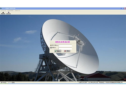
The centralized oxygen supply computer management system (remote meter reader software) introduction
Our company designs and manufactures the “computer remote meter reader management system ” which researches and develops on our own aiming at the needs of hospital's specific environment and specific function. It could address coding 99 flow meters at the same time in 1200 meters distances, and transmit the information to the Surveillance mainframe through the RS485 communication connection.
It could monitor the immediate flow, accumulation flow and the pipeline's pressure at any time, and also could set the bound of immediate flow and pipeline's pressure, ultra limits acousto-optic alarming.
the Surveillance mainframe possess the functions of data monitoring, data inquiry, data automaticly
preservation , printing and so on.

一、Installation
Execute “VB6.0”setup.exe documents of erection disc.
Install the Setup.exe system of driver disc into the computer.
二、System Setting
It Will use this system software's unit full title, using the input system parameter of oxygen to configure interface.
三、Basic Configuration
This function focuses on carrying on coding number between each different ward's meters and corresponding medical departments to make sure the joining time, And carries on addition, revision, deletion to the above things.
四、User Management
It distinguishes, increases or deletes the hospital management department.
五、Supervisory Control
The system may monitor various wards' meters in circulation and returns to the data to the computer simultaneously, demonstrating the pressure, the immediateflow, the accumulation flow and so on.
The system may preserve each wards meters' current accumulation flow figure to the database, for the purpose of later inquiry, reporting and printing .